Archive
Tower Crown Structure of the Queenstown Communal Permaculture Centre
Prototyping as a Design Development Tool:
Tower Crown Structure of the
Queenstown Communal Permaculture Centre
For this project I am using rapid prototyping technologies is to develop detailed design for the crown structure with the aim to gradually increase materiality and detail while reducing material use.
Introduction
The design project was conceived as a communal lifeline in Queenstown, Singapore in the event of a ruinous anthropogenic global warming and climate change episode in the not-so-far future.
Based on published studies by International Panel on Climate Change (IPCC), climate data made available by NASA and global energy and material consumption trends, a +2˚C scenario by the end of the next 50 years is very likely to happen, along with greater demand (due to increased global population numbers and the rapidly expanding middle-class worldwide) on essential resources which currently defines our civilization.
The most important of all resources – energy, which is taken for granted now with abundant fossil fuels controls the functioning of our entire world, from the most gigantic of multinational organizations to the individual resident of a rural village. A shortage of fuels will put pressure on the production of other essential resources for civilized living such as food and clean water – and nations had and will go to war to secure more of these resources for themselves.
In light of such daunting futures, what can a small island nation/city state with high population densities do for itself? Singapore will need to forge herself into a resource-resilient nation, starting at the communal level.
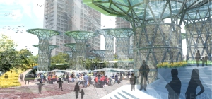
The Tower
The towers which populate the project site in Queenstown is deemed the most important element of the project. The towers will attempt to solve problems concerning the creation and the functioning of the proposed facility – as the main structural solution for the facility, the primary collector of solar energy and water for use on site, and also as a supplementary planting surface for smaller sized food crops such as beans and vegetables.
The Tower Crown Structure
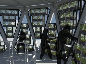
 The tower crown structure is the main apparatus with which solar photovoltaic energy and rainwater will be collected. Photovoltaic panels are deployed on the top side of the tower crown, collecting solar radiation and generating electricity for the facility’s use. The panels also functions as sunshades for spaces directly below it.
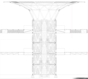
The tower crowns are shaped like a funnel which maximizes their rainwater catchment area, and then channel the water to treatment and storage tanks beneath the facility.
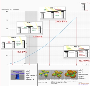
The shape, proportions and dimensions of the tower crown have been previously determined via parametric studies in a software called Houdini by a different member of the project team. The effects of self-shading among the tower crowns, theoretical solar collection potential and theoretical limit of steel structure span in between 2 towers were used to analyze and then select the form with the best compromise in between the three performance indicators.
Rapid Prototyping to aid in Tower Crowns’ Design development
My area of investigation for this project using rapid prototyping technologies is to develop detailed design for the crown structure with the aim to gradually increase materiality and detail while reducing/optimizing material use.
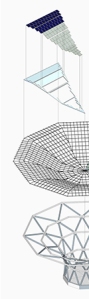
1st Prototype
The first prototype was a model made based on the funnel structure generated in Houdini. The dimensions of the tower and crown structure were replicated in Rhinoceros, and then mapped out as a series of panels on a 3d surface using Panelling Tools in Rhino. The structure was at this stage conceived as a precast-concrete shell structure.
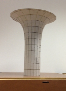
Being a design comprised of a series of shells/panels fused or joined together, the one option I chose for producing the first prototype was to unroll the panelled surface and to use the laser Eengravers to rapidly AND accurately cut out the templates which I will then assemble together. The model was put together using UHU glue and some discarded pieces of paper as backing sheets upon which I glue together the pieces.
The first prototype was a very solid construction, despite being made out of just grey straw boards. In retrospect, the first model was rough and very much heavier than the subsequent incarnations of the design/prototypes. This however proved to be a heavy structure and there were concerns that such designs may increase logistical loads of transporting the pre-fabricated concrete panels to site.
2nd Prototype
The second prototype model was that of a steel truss-tubes structure designed around the original dimensions of the tower and crown structure. The initial panel sizes of the previous prototype had to be revised. Subdivision/mapping of the crown/funnel surface using Rhino’s Panelling Tools was deliberately controlled to standardize the sizes of each truss tube members, which met with limited success. Member sizes on the crown structure inevitably became larger as we approach the larger, top-end of the funnel-shaped structure.
At this stage the prototype was still meant as a study/mock model hence I decided to produce the second prototype using the same method as the first.
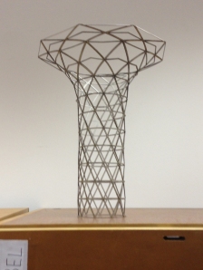
The resulting model is one that is significantly lighter compared to the first prototype, both visually and material-wise. At the time of this report’s writing, there is already considerable sagging and bending of some of the thinner members of the second prototype, causing the model’s shape to distort. I attribute this behaviour to moisture absorption of the grey strawboard. This presents a new set of realization to the tower’s design: thermal expansion of the steel tubes used to build the tower.
3rd Prototype
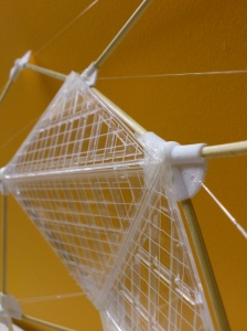
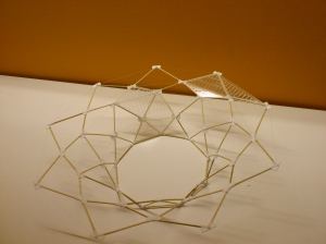
The third prototype is the next step into the detail design of the crown structure. With this iteration of the design I intended to use the secondary structure on the crown (which supports the PV panels) as the tensioning members for the crown structure, reducing the use of the relatively heavier truss tubes structures. The joints between the truss tubes also become hardpoints for fixing on the secondary structure.
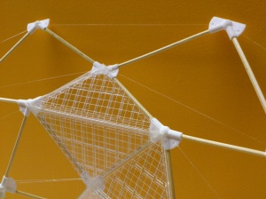
For this prototyping exercise I went ahead with using the Selective Laser Sintering 3D printing technique as offered in the EOS Formiga P100 3D Printer to produce the joints and then using 3mm thick bamboo skewers, cut to size as the truss tubes for this prototype model. They were secured together using hot glue.
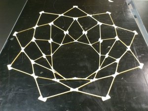
Cast acrylic sheets were made into the secondary structures using the laser engravers and then glued onto the 3D-printed parts. I did not make the acrylic panels for the entire prototype due to prohibitive costs of the acrylic sheets.
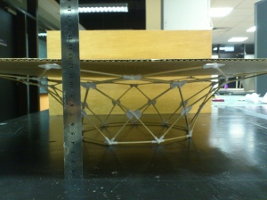
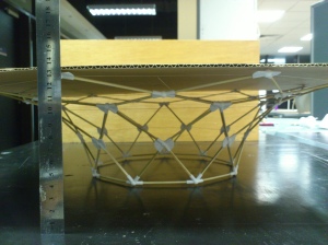
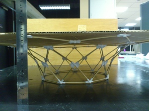
I then put the prototype to the test: placing loads (a 20mm thick plywood measuring 200mmx400mm) on top of the crown and measuring the deflection. As I did that, the thin acrylic members meant to take the tension loads broke. The structure did hold, however, due to the intrinsic flexibility and bending resistance of the bamboo skewers. The deflection was measured at about -12mm in the Z-Axis (the peripheral members of the crown was pressed down).
4th Prototype
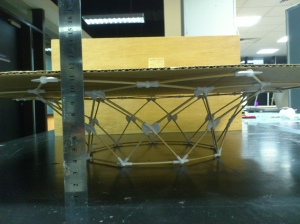
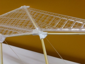
The fourth and final prototype presents the final iteration of the design. Learning from the previous iteration, I realized there needs to be a stronger tension member for the crown, while keeping structural weight penalties down. I looked to the possibilities of employing high-tension cables such as those used in suspension bridges to take up this job.
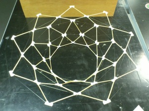
The prototype model for this iteration remained largely the same, using the same 3D-printed parts with just the addition of small holes to fit a thin nylon string through. I used 0.45mm thick nylon fishing strings to simulate the action of the tension cables.
A similar test was done to this prototype, using the same load. The structure held and deflection was measured at approximately -8mm in the Z-Axis, indicating a slightly better performance.
The revised, thickened acrylic panels and secondary structures were then added onto the structure. There were some discrepancies between the laser-cut panels and the space allocated for the panels, likely due to mistakes and inaccuracies when cutting the bamboo skewers to size.
Conclusion
Rapid prototyping provided me with vital tactile and experiential feedback (as well as allowing me to experiment on the prototype models) where digital design is deficient in providing such information. The models aided me to gradually add-on details and systems and complexities to the model, helping me to advance faster in terms of detailed design for the crown and its components.
There is, however, still penalties when it comes to accuracy in spite of such high-tech machines – particularly due to human errors during assembly of the machine-produced parts. The machines are prone to inaccuracies of its own due to excessive use and some of its moving parts being heavily worn and becoming loose.
Despite all that, rapid prototyping techniques provided a way to quickly hold in my hands the object I designed and obtain from it valuable tactile feedback and even allowed me to conduct simple experiments on them, aiding along the design process.
