Dfab Exhibition: Form follows Performance
HYPERBOLIC DIA-FRAME
Structure demanded a very stable hyperboloid form as internal structure. Strength of mesh structure is directly propotional to the distance between vertical member. Structural Simulations showing stress distribultion maximum and minimum over the hyperbolic structure with pentagonal opening as stable mesh form.


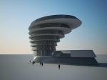


Skin analysis involved process of major solar incident radiation calculation and optimization of facade panels. Curvilinear floor plates created a challenge to achieve equal no. of panels. Upward conical extrusion of plates result with more optimised panels as well as self shading structure.
Thanks Ping lei to upload my project !!
Command explored:
Ptpanelgridcustom, Ptfinedges, unrolledges
http://www.youtube.com/watch?v=G2iq3MTz4oo (helpful videos to understand panelling tools, which is most important for fabrication)
VINOD RAJPUT
Caving-in:tri-grid ribs for mass-customisation biomimicry


Tracing the forces translated at each diaphragm.
Top two images shows the difference between the stress distribution with and without cores.

Digital fabrication Flow.
The last two steps (contouring Rhino3D solid, unrolling/ re-orienting each rib on a sheet for lasering+ labelling)were extremely time consuming for such a scale of mass customisation.
Rhinonest has a tool that combines the end process into one! i.e.
-3D contour slice
-unroll/re-orient on flat plane
-label
Video shows the old version of 3d contour http://www.rhinonest.com/video/rhinonest-20-slide-3d-command or this
http://www.rhinonest.com/video/rhinonest-forum-answer
Noticed that you need to have a very powerful processor(they used quad in the 2nd video) You can even customize the way of labelling if different levels exists! But Rhinonest is a very sensitive plug-in. When I used the postition optimization tool, curves that were not closed were not identified as an object. So Rhinonest contour should require a solid of closed polysurface too!

Assembly of 3-directional ribs

Systems: Infill-floor system and Angled facades with repetitive modules of different combinations. Window mullions as secondary loadbearing members

Structural Shading


#shading device that acts as a structural member as well.
#column thickness pattern (cross-sectional shape) to determine structural distribution
#shape of column profile to determine shading
#building outline derived based on sunshading and Ecotect simulations
#column/grid pattern based on Algor simulations
Difficulties encountered: In the case of this project, due to the numerous curved surfaces, Algor simulations could only be possible by meshing the entire model as a solid and not as planes. Sometimes the meshing does not work until the mesh size is reduced such that it is possible to mesh small areas/ sharp ends of each curved facet, and this in turn becomes a very time-consuming process of meshing.
Michelle :]


1. Stress Distribution Image of a typical floor plate
2. Using this grasshopper definition, translate the image into points with varying displacement in the Z direction
3. Grasshopper can help you transform points to surfaces then to ribs
4. Interior Perspective
5. Final Model
ys
Parametric Dia-Grid: Thickness/Depth


One of the greatest issues i faced was doing algor analysis. In short, algor doesn’t like many surfaces. The reason being it interrupts with its meshing engine. The workaround is of course to use as little surfaces as possible. How i did that was to create voids instead of the real diamond panels that consisted of 4 surfaces each (if you have 100 panels, that makes 400 surfaces and that would easily make algor crash). After creating the voids, i “booleaned” it away from a huge surface (say the east facade), so that what remains is a huge surface with many diamond holes in it. That way algor knows how to mesh easily. Calculation time is also GREATLY REDUCED. (i would say exponentially)
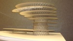
Cairo Pentagon Structural Lattice


Use Cairo pentagon as a basic geometry, generating a dynamic spatial arrangement out of a rigid grid system.
The lattice is formed when layers of Cairo pentagons stack on one another.
Thus the veritcal deadload at a certain height increases as the number of layers.
The thickness of the column is thus modified according to the structural loading requirement.
Tri-grid Structural Shear


concept
– using the facade as the primary structural element in a geometrically challenging building
– using a basic structural tri-grid structure on the building facade
– to increase truss density in response to facade stress distribution simulation in algor
difficulties
– difficulty in automating the truss density using grasshopper image sampler to achieve a complete tri-grid structure.
i.e. ensuring each module consists of only tri-grid members
Columns’ Accommodation


Uni-column Building
A simple concept of keeping the columns to the minimum. One.

Using Algor, I have found the stress distribution on a normal floor plate.
Depth of the floor plates at different locations determined by inserting the following image into Grasshopper.
Floor plates ribbed for fabrication, also using Grasshopper.

Simulation result of floor plate.
